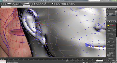
The ear was a very complex part to model so the rest of the head was isolated. In Photoshop the main outline of the ear and the contours were drawn around in the same way that the face was. It was very hard to divide the ear up in to four sided shapes due to its complexity. After editing in Photoshop, the image was saved and then reloaded in the material editor within 3Ds Max to allow the changes to be visible on the reference planes.

The ear was then traced around using the line tool with the snap toggle selected and set to vertex (making sure it was set to corner in initial type and drag type). One of the lines was then converted into an editable polygon and the rest of the lines attached to it.
The vertices were then moved along different axis to line up with the reference images. The outer vertices were moved and then the next ring of vertices. The middle vertices were tweaked using the perspective view in one window and a front orthographic view in another window.
To get more detail around the indents in the ear the chamfer tool was used to add more edges. The collapse tool was used to delete excess vertices created at the corners of the chamfer. This process was repeated to build up the detail of the ear.
The outer edges of the ear were selected and whiles holding shift dragged back to create the depth of the ear. This was then repeated but while the scale tool was selected to make an edge that could be connected to the head.
The ear was then attached to the head and then additional vertices were added to the head by selecting edges and holding down shift and dragging them to the back of the ear. The target wield tool was then used to join up the vertices. To make sure there were no unattached vertices the weld function was used.
When the turbo smooth was applied the vertices were tweaked to best match the shape of the ear.
This is the final render so far.


No comments:
Post a Comment