Wednesday, 19 October 2011

Setting up the bump map

A copy of the uvw map material was made and in Photoshop


Under the image tab, adjustments was selected and the levels were adjusted so that the black and the white markers were at the start of the each part of the graph.


Under the filter tab highpass was selected and the pixels radius was set to 3. This would define the bump map in 3ds Max.


The image was loaded into the bump map and the amount was set to 15. Some of the outline of the face was present in the map, so theses were edited in Photoshop using the clone tool.


The Bump map didn't look very realistic so a mix filter was added to the bump. In the bump filter the bitmap was selected and mix was selected, then keep old bitmap as sub map was pressed.

The colour #2 was selected and add noise was pressed. It was set to fractal and the size was set to 0.01.

The mix was then set to 100 so that only the noise map could be shown. The face was then rendered to compare the difference. The bump texture was too large so the x and y tiling were set to 4.


The mix amount was adjusted until the texture looked as accurate as possible to the skin texture. The final mix was 60.


Final render of the head with Bump texture set


Thursday, 13 October 2011

Face with ears and adjusted UVW map

After lots of tweaking and use of the patch tool the face material is nearly complete.


Applying reference image to UVW map


The Render of the map was opened in Photoshop and a new layer added. A bright colour was added then a layer mask was used to select the map lines and apply them onto a separate layer. Sections of the reference image were selected and placed onto the map. The transform tool was used to distort the images and make them fit the map.


This Photoshop file was then added to a new material in 3ds max and applied to the face.


The parts of the face taken from the reference images were blended together using the clone stamp and the patch tool some of the parts needed the hue & saturation and the brightness & contrast adjusted to match together smoothly.


An action command was set up to save the image and automatically hide the guide layer so that when the Photoshop file is edited and saved 3ds max updates the material and the guide is not shown on the material.


A section of skin was copied from the neck as the ears were not very visible from the reference images. The skin was stretched over the ear map to create the best match of skin colour for them.


Applying the UVW to materials

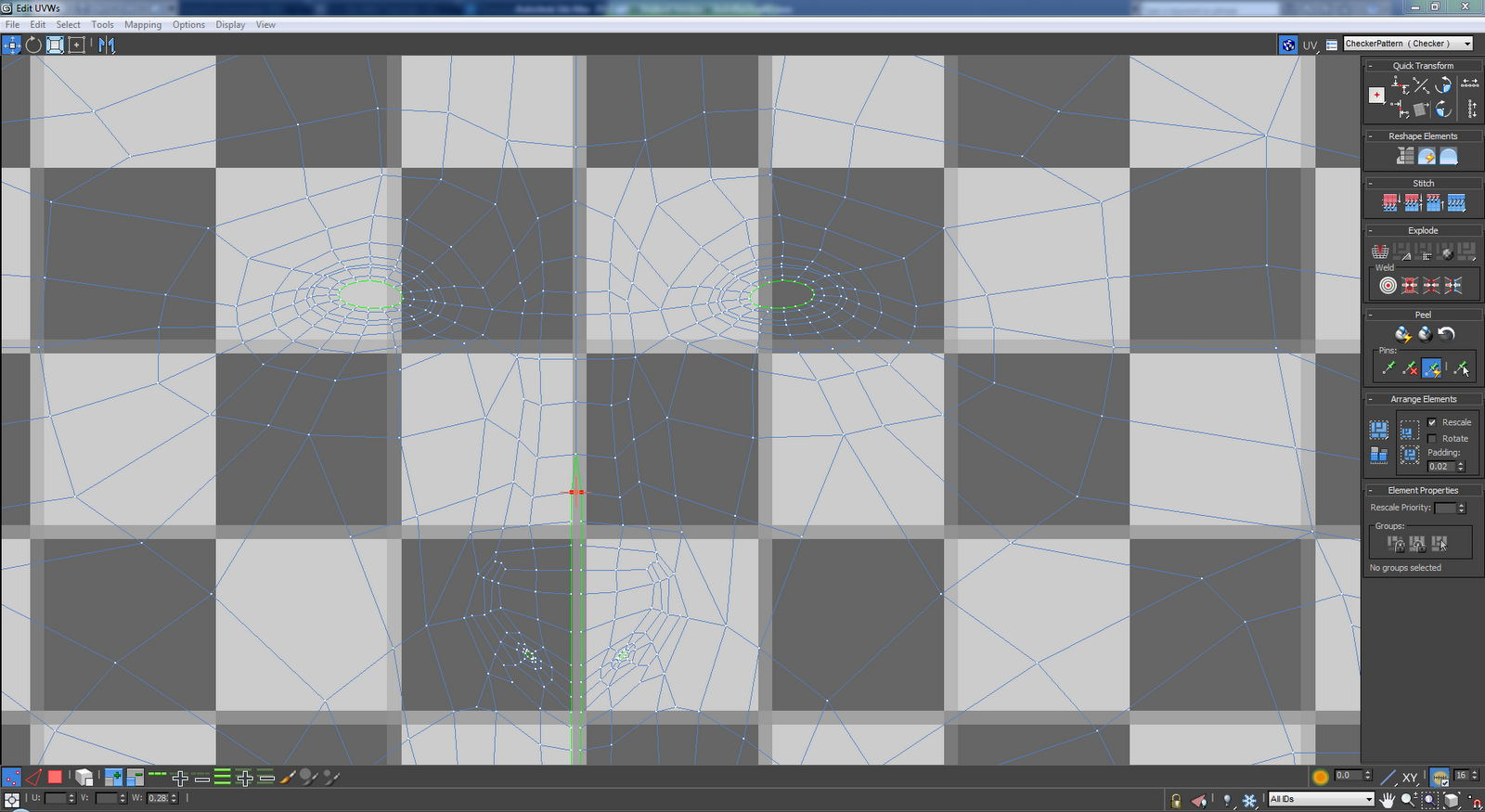
To get an even flow of the material over the head a simple checker material was added to the face and made visible in the viewport it was adjusted until it was an approximate size of the polygons. The UVW map vertices were tweaked until the checker pattern was uniform. This was done making the quads as even in shape as possible and avoiding harsh angles.


When the UVW map pattern looked correct it could be rendered ready for editing in Photoshop.


Evenly shaped polygons UVW.


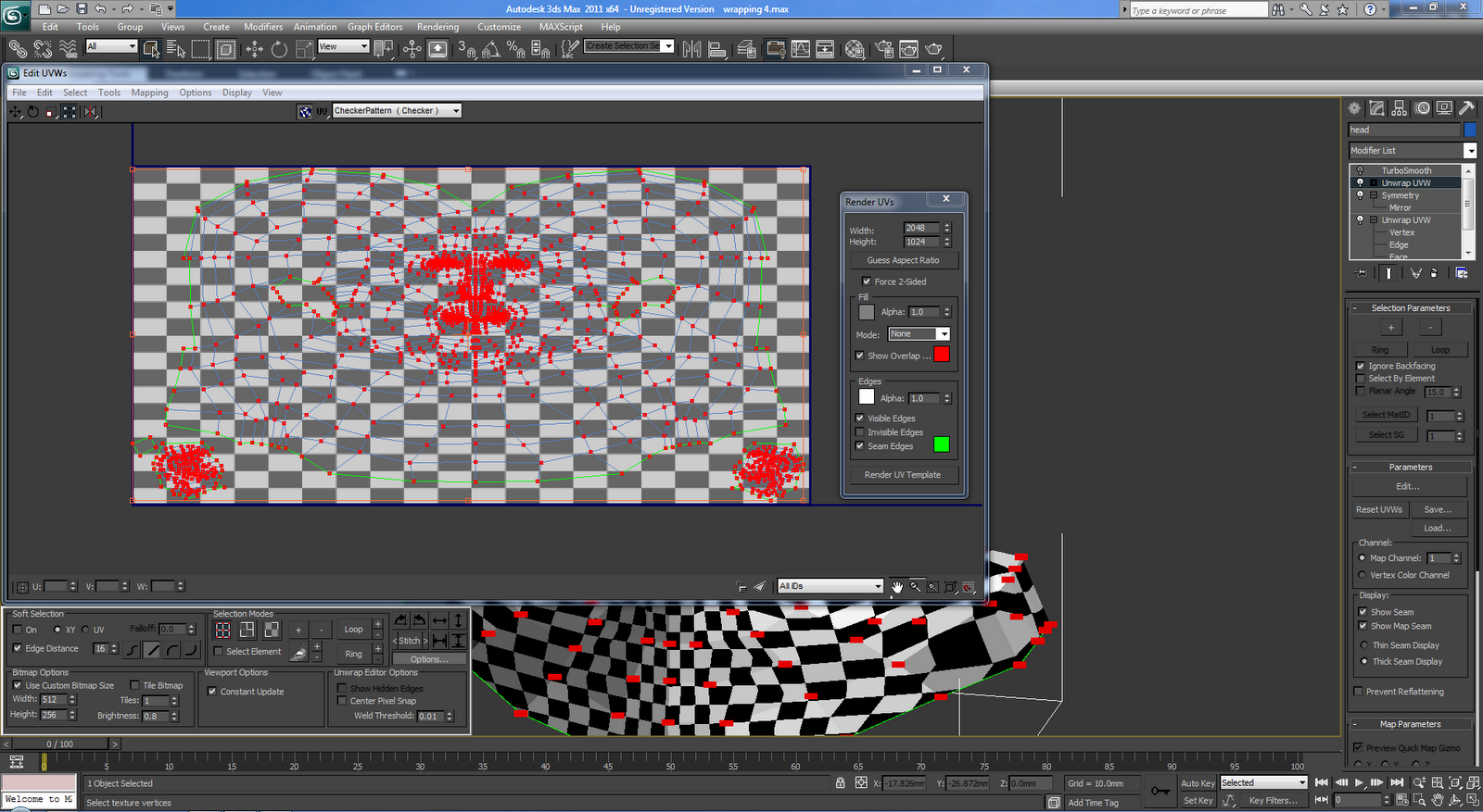
To render the UVW a width of 2048 and height of 1024 was entered. The mode was set to none so that a black and white map of the face was rendered.


This is the render of the UVW map it can be opened in Photoshop ready for applying the material image.


Setting the render type to normal produces a colour shaded map which can help to show how the material image can be applied to the map.


Unwrap uvw

After all the modelling had been completed it was time to think about actually applying materials to the face. As the face has so much detail It made scene to use a photo of the face as a material. To do this The unwrap UVW modifier needed to be used. This creates a 2d map of the face that the material can be added to.

The first step was to turn off turbo smooth and the symmetry modifier. Then the whole face was selected apart from the ear (this would be done at a later stage due to its complexity). There are several bugs in 3DS 2011 Max; one of which are in the Unwrap UVW modifier. Every time the polygons on the face were selected for unwrap UVW, the program crashed and shut down. To over come this 3DS Max 2012 was installed.


When the polygons on the face were selected cylindrical was selected under map parameters. The cylinder was set to the axis that wrapped the cylinder around the face. It was scaled to the correct size and moved to the centre of the head.


Edit UVWs was selected and filter selected faces was pressed. Constant update was selected to view a live update in the view port of the map. The relax feature was used to space the map out to get a more understandable map. Individual polygons were moved around to achieve a usable map. Select inverted and overlapping faces was used to make sure the map laid flat.


Saturday, 8 October 2011

Making the ear

The ear was a very complex part to model so the rest of the head was isolated. In Photoshop the main outline of the ear and the contours were drawn around in the same way that the face was. It was very hard to divide the ear up in to four sided shapes due to its complexity. After editing in Photoshop, the image was saved and then reloaded in the material editor within 3Ds Max to allow the changes to be visible on the reference planes.


The ear was then traced around using the line tool with the snap toggle selected and set to vertex (making sure it was set to corner in initial type and drag type). One of the lines was then converted into an editable polygon and the rest of the lines attached to it.


The vertices were then moved along different axis to line up with the reference images. The outer vertices were moved and then the next ring of vertices. The middle vertices were tweaked using the perspective view in one window and a front orthographic view in another window.


To get more detail around the indents in the ear the chamfer tool was used to add more edges. The collapse tool was used to delete excess vertices created at the corners of the chamfer. This process was repeated to build up the detail of the ear.

The outer edges of the ear were selected and whiles holding shift dragged back to create the depth of the ear. This was then repeated but while the scale tool was selected to make an edge that could be connected to the head.


The ear was then attached to the head and then additional vertices were added to the head by selecting edges and holding down shift and dragging them to the back of the ear. The target wield tool was then used to join up the vertices. To make sure there were no unattached vertices the weld function was used.


When the turbo smooth was applied the vertices were tweaked to best match the shape of the ear.


This is the final render so far.


Making the neck

The polygons were constantly tweaked using the reference images. Alt + X was pressed to make the polygons transparent. To create the neck and shoulders edges were selected and whilst holding shift they were dragged in the desired direction which made a new edge. This process was repeated until there were enough polygons to make up the shape of the neck. The vertices were dragged to the correct place using the reference images.